Media/WebRTC/WebRTCE10S
Introduction
The WebRTC architecture for desktop (Media/WebRTC/Architecture) is based on a single process model where we can directly access platform resources from the WebRTC code. B2G, however, has a split process architecture (B2G/Architecture) where the renderer/content process runs in a sandbox and has limited access to platform resources. Generally, it accesses them by doing IPC calls via https://developer.mozilla.org/en-US/docs/IPDL
The current architectural split is shown below:
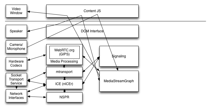
In this diagram, physical devices are shown on the left and components of the browser are on the right. Note that we show a number of arrows going through the DOM/JS layer. The implication is that MediaStreams are mediated by the DOM/JS layer. I.e., JS is responsible for plumbing MediaStreams between gUM and the PeerConnection and between the PeerConnection and video/audio tags. This doesn't mean that the media actually flows through the JS, however.
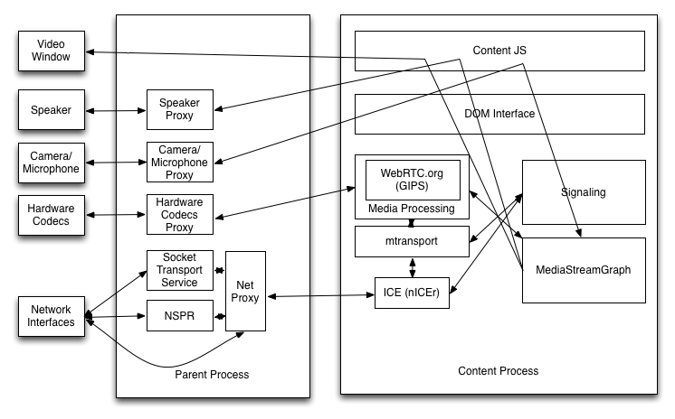
Below we show a proposed process split with E10S:
System Resources to be Proxied
The following system resources need to somehow be made accessible to the renderer process.
- Video rendering (accessed via a video tag) [TODO: Is this actually a system resource? Not clear on what the display model is.]
- The speaker (accessed via an audio tag)
- The camera and microphone
- Hardware video encoders and decoders (if any)
- The network interfaces
In addition, we use the Socket Transport Service (STS) to do socket input processing. We create UDP sockets via NSPR and then attach them to the STS in order to be informed when data is available.
Input Device Access (getUserMedia)
Output Access
Network Access
All networking access in WebRTC is mediated through the ICE stack (media/mtransport/third_party/nICEr and media/mtransport/nr*).
From a technical perspective, the requirements look like:
- The ability to send and receive UDP datagrams with any valid local address and any remote address.
- The ability to enumerate every network interface.
- The ability to have events happen at specific times.
Below is a schematic diagram of the interaction of the ICE stack with the rest of the system which shows how things actually work.
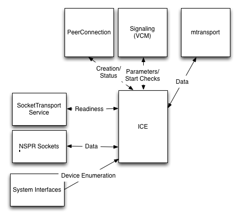
As before, the boxes on the left signify the currently protected operations.
There are two natural designs, discussed below.